
LSC Smart Connect Smart Floor Lamp
LSC Smart Connect Smart Floor Lamp
This guide applies to the LSC Smart Connect Smart Floor Lamp sold by Action.
| Property | Value |
|---|---|
| Brand | LSC Smart Connect |
| Retailer | Action |
| Product | Smart Floor Lamp |
| Article number | 3221699 |
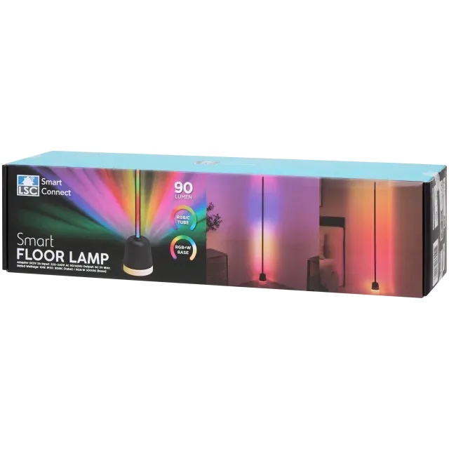
The lamp features two independently controllable lighting zones. The main light section is an addressable LED strip, allowing animations and individually controlled LEDs. The illuminated base uses a conventional RGBW LED, providing independent RGB and white light control.
The device can be flashed using LTChipTool and a 3.3 V USB-to-UART adapter.
UART flashing
-
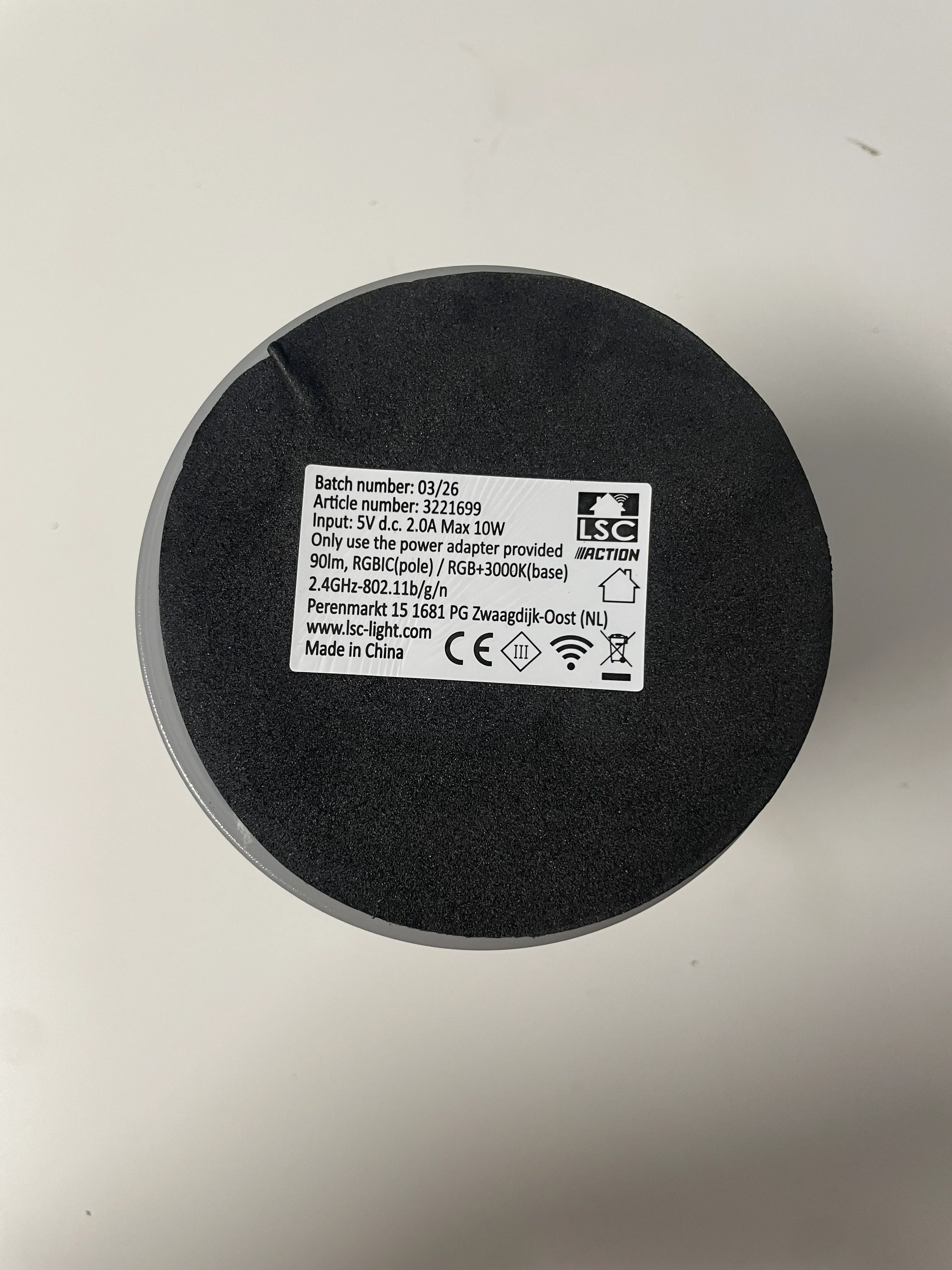
Turn the lamp upside down.
-
Carefully remove the large foam pad from the bottom of the base.
-
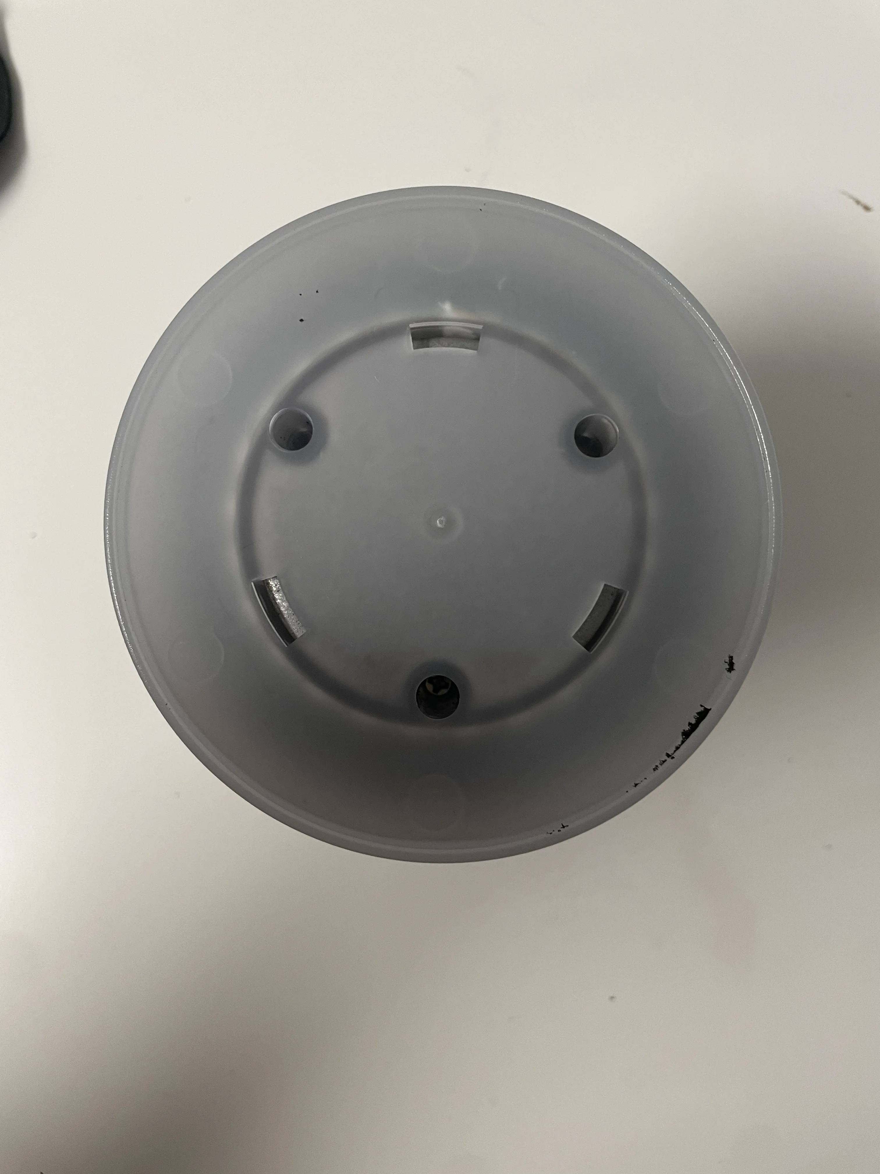
Remove the three screws underneath the foam pad.
-
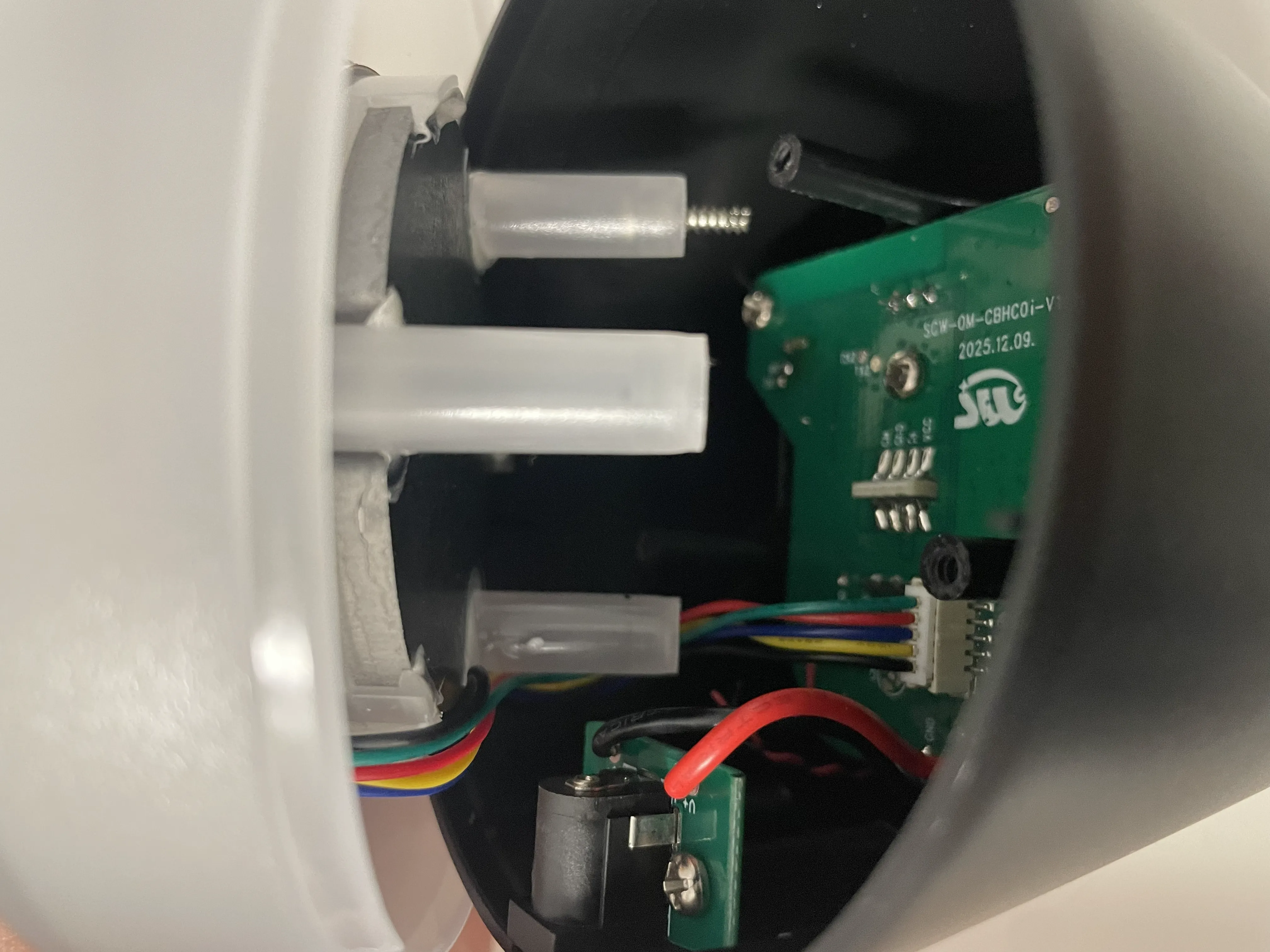
Carefully open the base to access the PCB.
-
Disconnect the connector between the base and the PCB. Hold the connector itself instead of pulling on the wires.
-
Connect the USB-to-UART adapter to the programming pads.
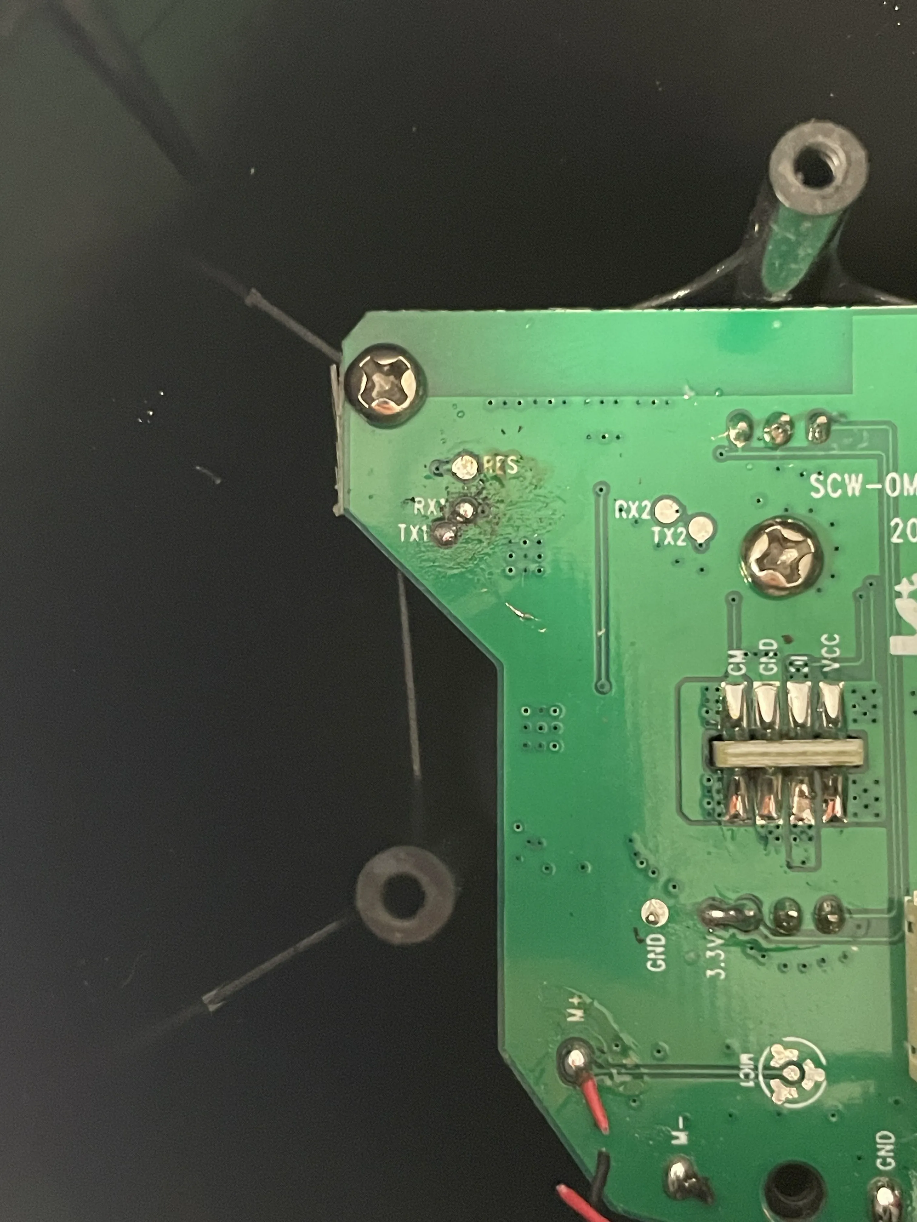
USB-to-UART Lamp TX RX1 RX TX1 GND GND The programming pads can be accessed either by soldering temporary wires or by using pogo pins. Pogo pins are recommended, as they do not require any permanent modification to the PCB.
-
Build your ESPHome configuration and download the UF2 firmware image. In LTChipTool, select the downloaded .uf2 file, leave the flash address at the default value of
0x0, select the correct serial port, and start the flashing process. Once LTChipTool is waiting for the device, either power on the lamp or briefly short the RESET pad to GND. LTChipTool should detect the bootloader and begin flashing automatically. -
Wait until flashing has completed successfully.
-
Disconnect the programmer, reconnect the cable between the PCB and the base, and reassemble the lamp.
Warning
Use only a 3.3 V USB-to-UART adapter. Applying 5 V may permanently damage the device.
LTChipTool
For detailed installation and usage instructions, please refer to the official LibreTiny LTChipTool documentation.
GPIO configuration
| Function | GPIO |
|---|---|
| Base Red | P8 |
| Base Green | P24 |
| Base Blue | P9 |
| Base White | P26 |
| Addressable LEDs | P16 |
| IR Receiver | P23 |
| Capacitive Button | P22 |
Basic configuration
esphome:  name: lsc-smart-connect-floor-lamp  friendly_name: LSC Smart Connect Smart Floor Lamp

bk72xx:  board: generic-bk7238-tuya
logger:
wifi:  ap:
light:  - platform: beken_spi_led_strip    name: Main    pin: P16    id: light_beken_spi_led_strip_1    chipset: SM16703    num_leds: 96    rgb_order: GRB    effects:      - addressable_rainbow:      - addressable_twinkle:  - platform: rgbw    name: Base    blue: blue_base    green: green_base    red: red_base    white: white_base    id: light_rgbw_1    icon: "mdi:lightbulb"    restore_mode: ALWAYS_ON
output:  - platform: libretiny_pwm    pin: P9    id: blue_base  - platform: libretiny_pwm    pin: P24    id: green_base  - platform: libretiny_pwm    pin: P8    id: red_base  - platform: libretiny_pwm    pin: P26    id: white_base

remote_receiver:  id: ir_rx  pin:    number: P23    inverted: true    mode:      input: true      pullup: true
binary_sensor:  - platform: gpio    name: Touch Button    pin:      number: P22      mode:        input: true        pullup: true      inverted: true    id: binary_sensor_gpio_1    on_click:      - then:          - light.toggle: light_beken_spi_led_strip_1
Notes
- Supports two independently controllable lighting zones.
- Main light section uses addressable LEDs.
- Base uses a conventional RGBW LED.
- Flashing requires opening the device.
- This guide is based on the Action retail version with article number 3221699.